PCB Crane
When I saw Giuseppe Finizia's design of PCB crane I knew I need it. It would make debugging of your new hardware and software so much easier. You just connect power and as many pins as you want (or as many as your oscilloscope or logic analyzer supports) and you are ready to go! No more holding three probes in one hand, power supply with the other and then using your nose and mouth to interact with an oscilloscope and the device itself. The solution is finally here.
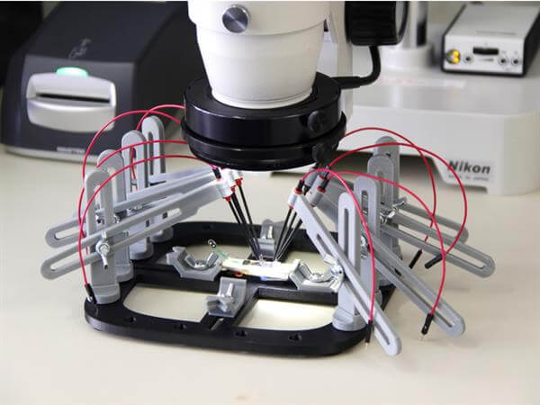
I quickly look more deeply into the design and noticed a few (not really) issues. Firstly, I didn't like those spring loaded test probes, because they are relatively expensive and too chunky. I have worked before with those ones which can be cheaply found on an ebay and can fit nicely into the 0.1inch (2.54mm) headers. Next minor thing that I didn't like is that it use different screws sizes and wing nuts. I think it is easier to modify 3D model than searching for the correct screws, nuts, and bolts. Last but not the least, I didn't like that some of the parts needs to be printed with support (base pin), so I designed it to be printable without them. And that is it.
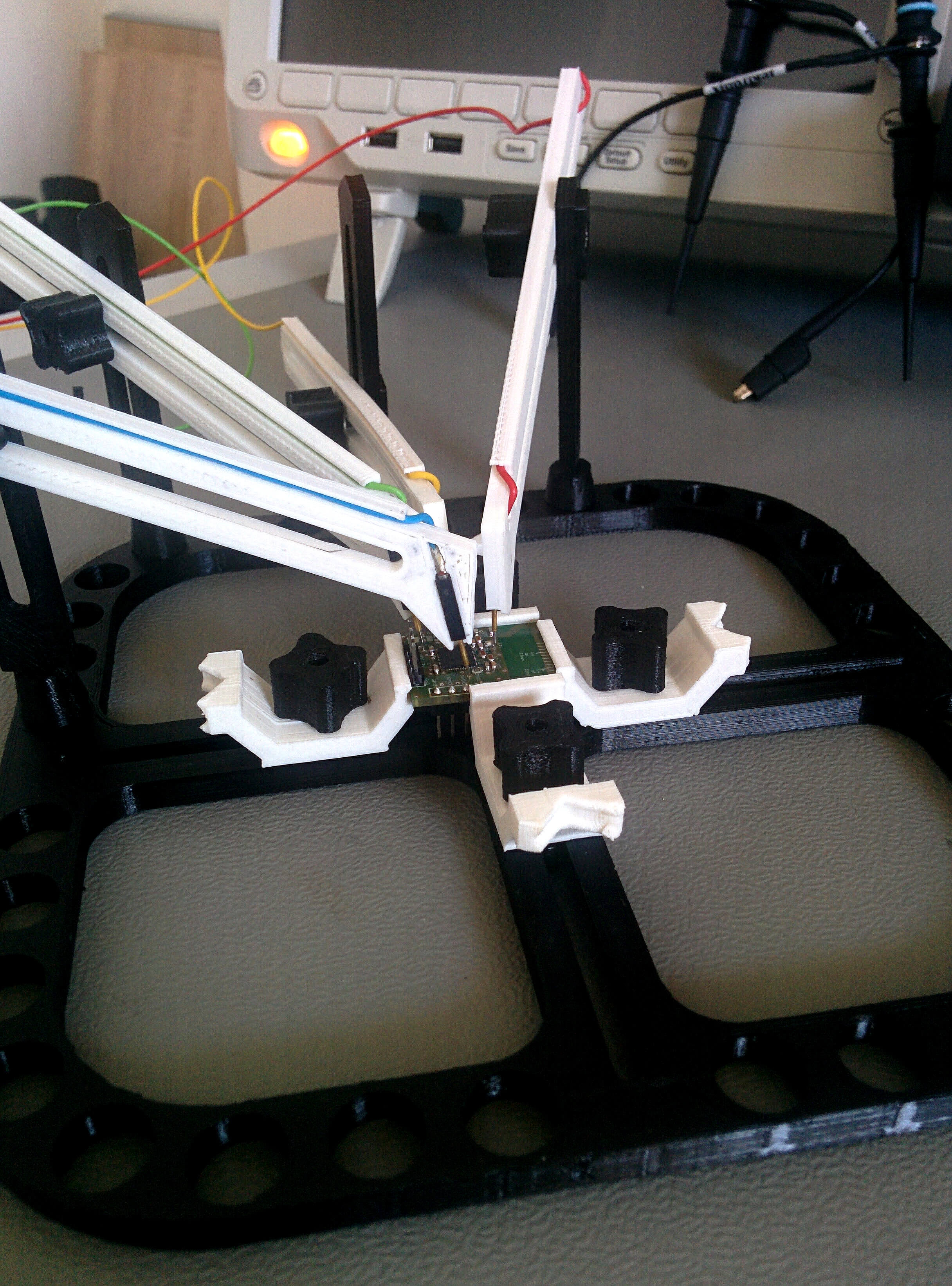
I only kept the PCB holders from the original design (white ones). I only tilted them for 90 degrees, so they can be printed without supports. Otherwise, everything else is designed from scratch. Don't get me wrong. The Giuseppe design is really good, but I can't help myself when I see a room for improvement. And I also like to make stuff :)
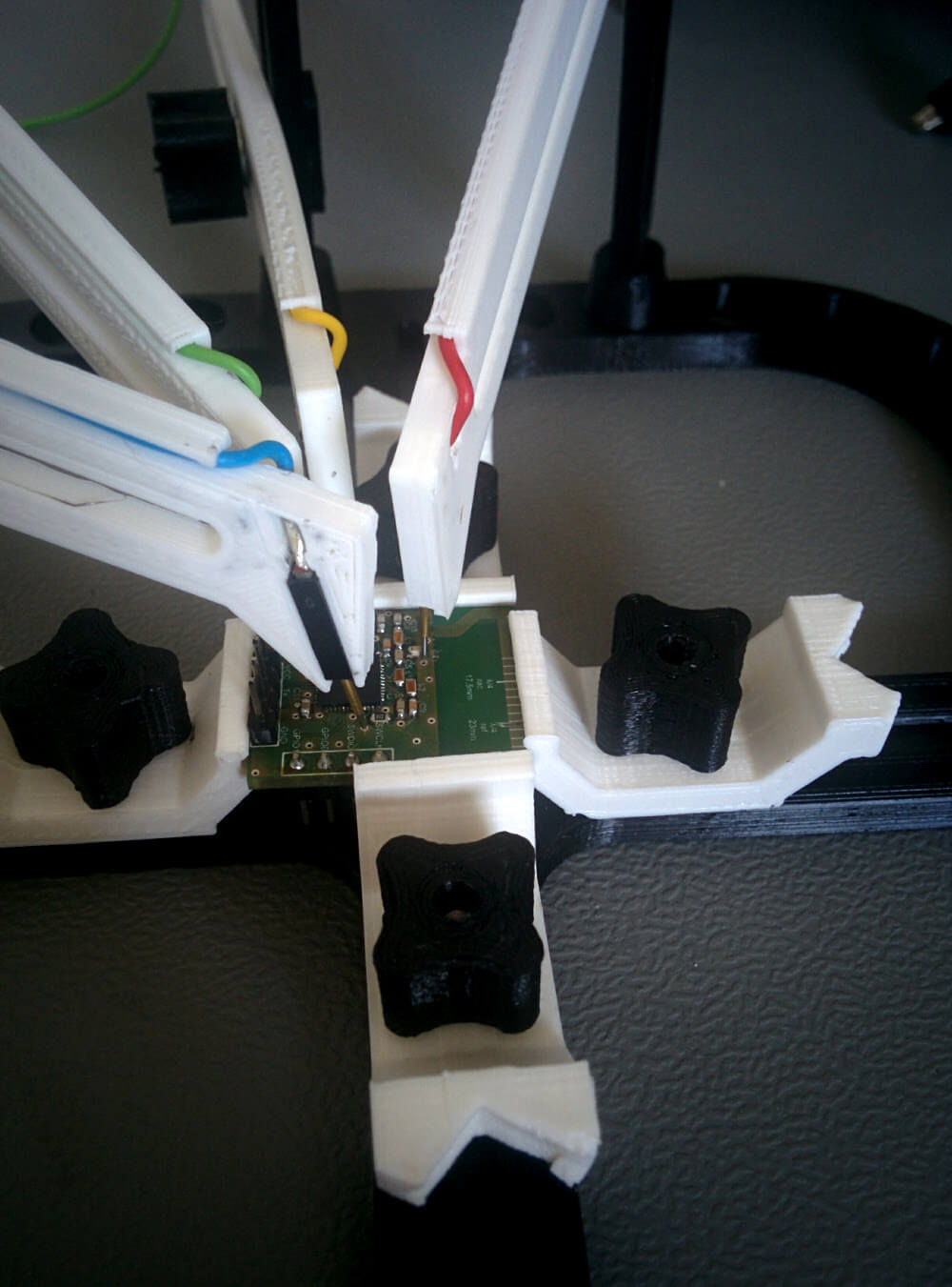
At first, it is quite hard using it, but after a little practice, it becomes a piece of cake (not literally, sadly). To me, the easiest way was to squeeze spring loaded pin to the correct place with one hand and then stabilize the vertical holder onto the base and tighten the screw with the other. For comparison, components on the upper image are 0402 (1x0.5mm). I have to say it is a joy working with it. If you want to print it yourself you can find all of the files on Thingiverse free of charge.